-
 Figure 20.1Method for manual assessment of heel counter stiffness.
 -
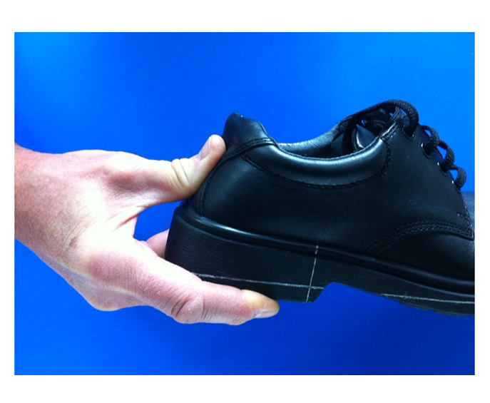
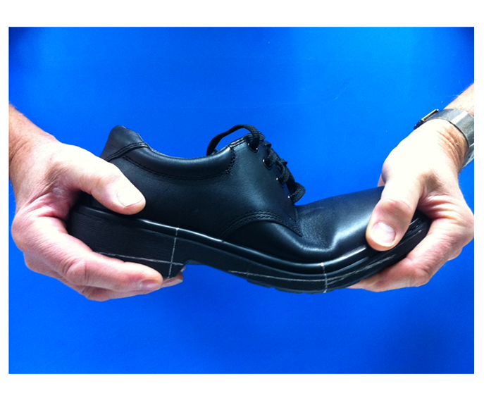
 Figure 20.2Method for manual assessment of flexion stiffness.
 -
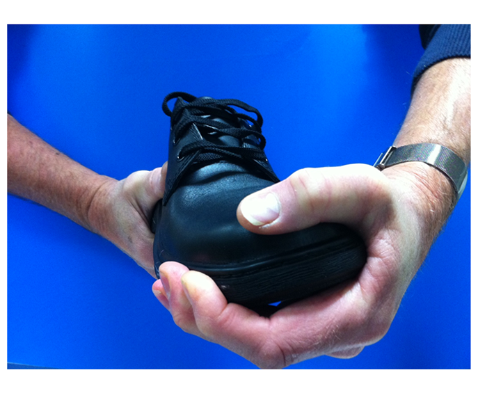
 Figure 20.3Method for manual assessment of torsional stiffness showing inversion of forefoot.
 -
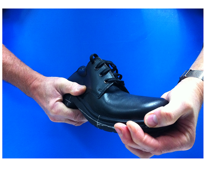
 Figure 20.4Method for manual assessment of torsional stiffness showing twist through length of the shoe.
 -
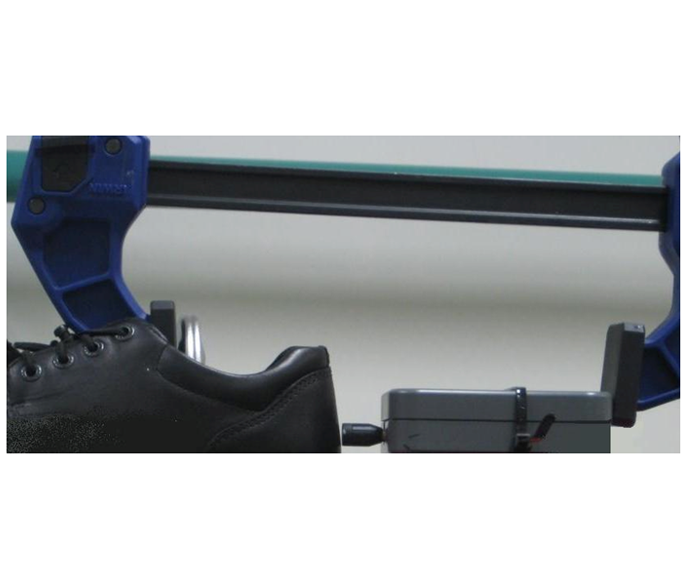
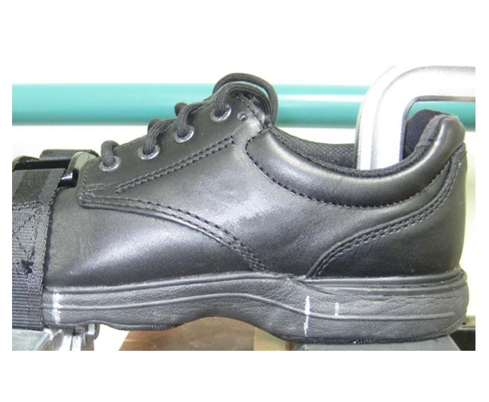
 Figure 20.5Setup for heel counter stiffness test rig showing first clamp in throat of shoe to maintain stability and second clamp with trigger grip providing compression through force gauge.
 -
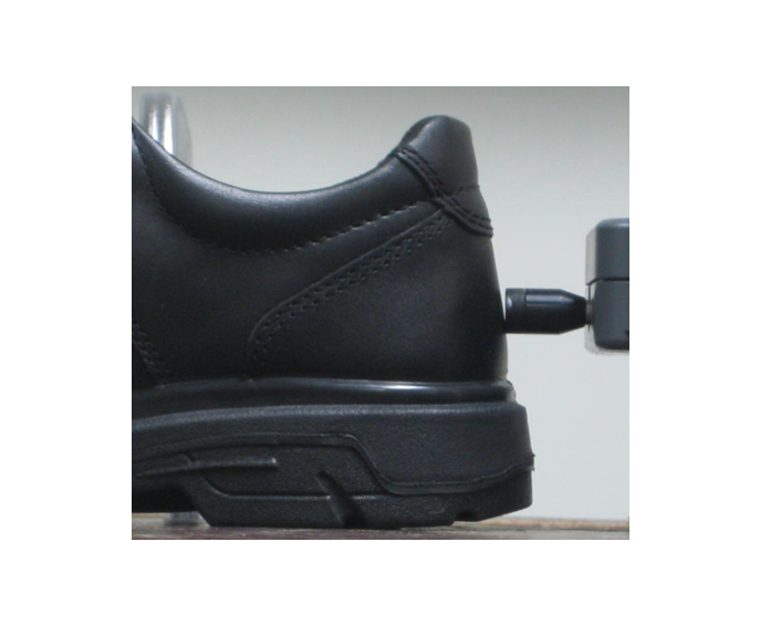
 Figure 20.6Alignment of soft-faced at posterior aspect of heel counter.
 -
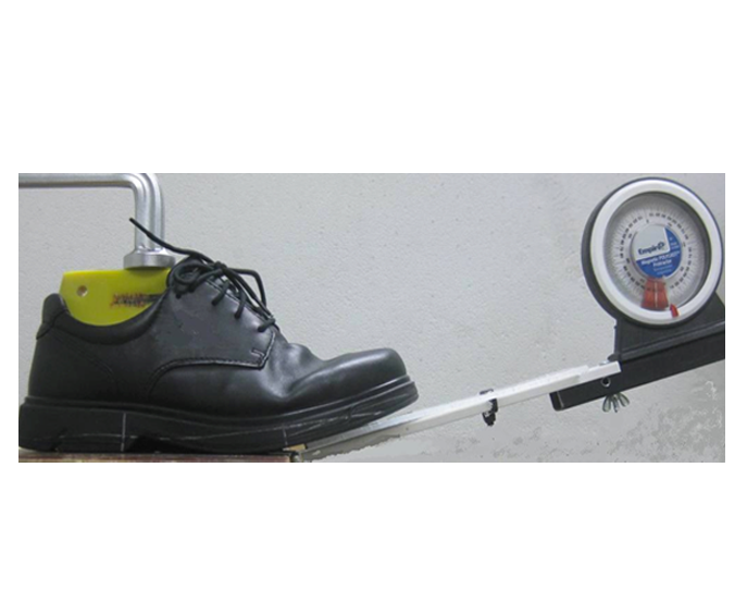
 Figure 20.7Flexion stiffness test rig setup showing restraining clamp acting through truncated last and hinged platform with inclinometer.
 -
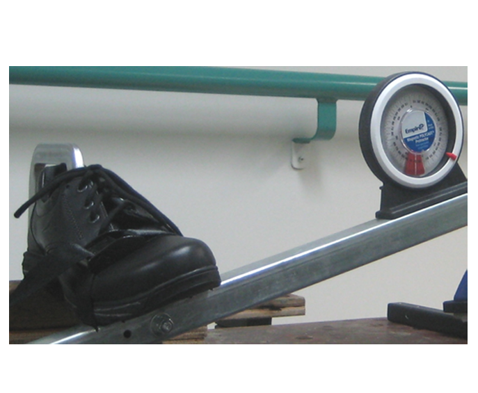
 Figure 20.8Torsional stiffness test rig setup showing front platform with central axis of rotation.
 -
 Figure 20.9Torsional stiffness test rig setup showing clamp to grip heel and restraining strap for front platform. Note that the shoe is located according to 30% and 66% marks.
 -
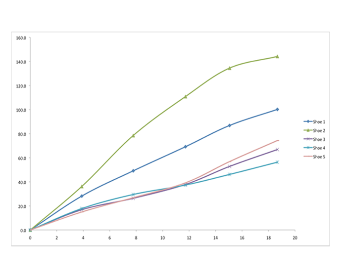
 Figure 20.10Example of heel counter stiffness curves obtained for a group of five school shoes.
 -
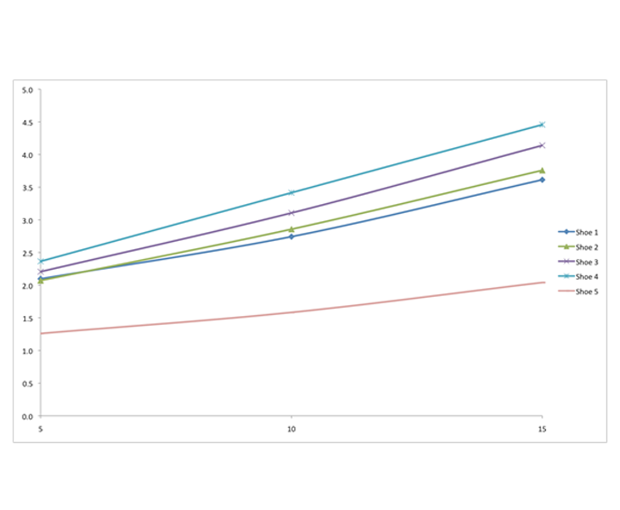
 Figure 20.11Example of flexion stiffness curves obtained for a group of five school shoes.
 -
 Figure 20.12Example of torsional stiffness curves obtained for a group of five school shoes.
 -
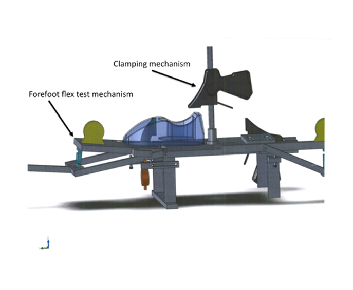
 Figure 20.13Design concept for an integrated, stand-alone test rig showing main clamping mechanism and flexion test mechanism.
 -
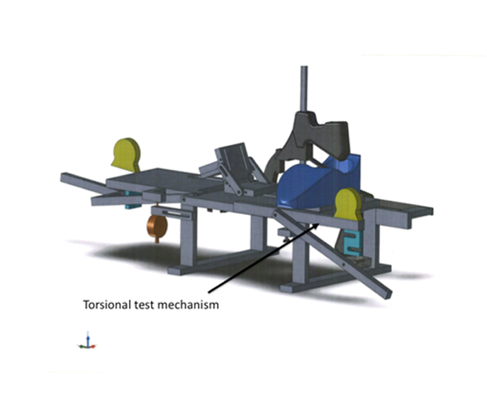
 Figure 20.14Design concept for an integrated, stand-alone test rig showing torsion test mechanism.
 -
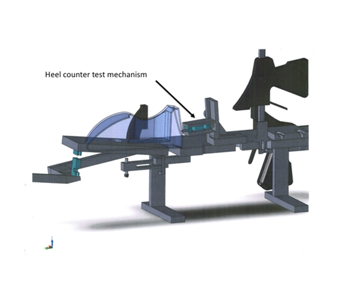
 Figure 20.15Design concept for an integrated, stand-alone test rig showing heel counter test mechanism.