-
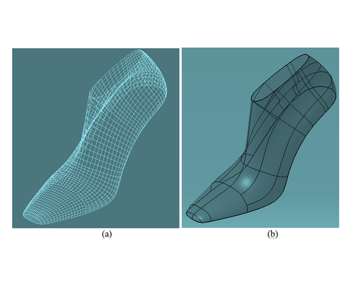
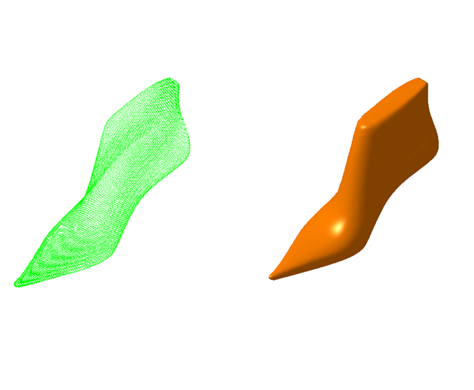
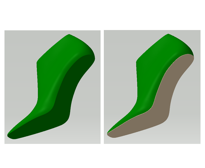
 Figure 10.1(a) A mesh-based surface model of a shoe last (b) A Boundary representation based analytical model of a last.
 -
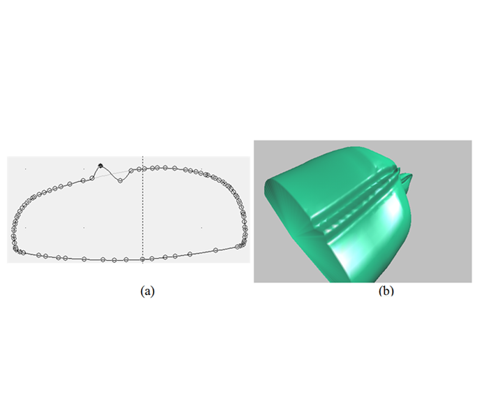
 Figure 10.2(a) A cross-section curve on a last model is modified to introduce a localized variation (b) Effect of the shape modification on the model is highly un-smooth.
 -
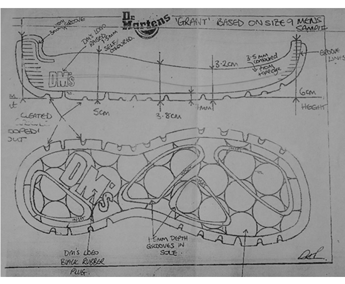
 Figure 10.3Sketches of a shoe sole indicating a design variation based on an earlier model
 -
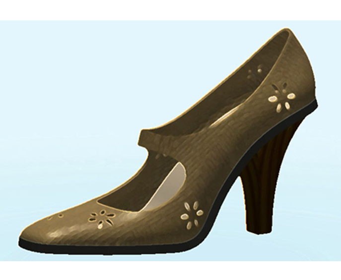
 Figure 10.4Sketch of a new style made on an image editor
 -
 Figure 10.5(a) Point cloud data of a last (b) Tessellated model of the point cloud
 -
 Figure 10.6Tessellated model is subdivided into patches by forming intersection curves. The intersection curves are subsequently smoothed
 -
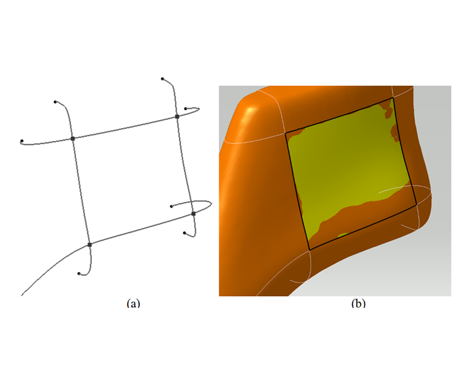
 Figure 10.7(a) Bounding curves of a subset of the last surface. As a consequence of the smoothing process in Step 2, pairs of curves may not intersect at all, so the smoothing operators must be constrained to guarantee that indeed the curves in the two directions intersect at the points shown in red dots. (b) A smooth surface is fitted to interpolate the bounding curves as well as the relevant scanned points in the region.
 -
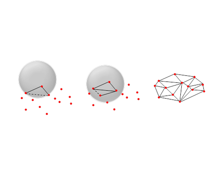
 Figure 10.8The ball pivoting algorithm: the input is a point cloud (red dots) and the ball radius (a) The ball rests on a seed triangle; the pivot edge is shown as a dashed line; (b) the ball pivots to add a triangle; (c) a possible outcome of the algorithm, with a triangulated surface.
 -
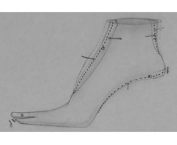
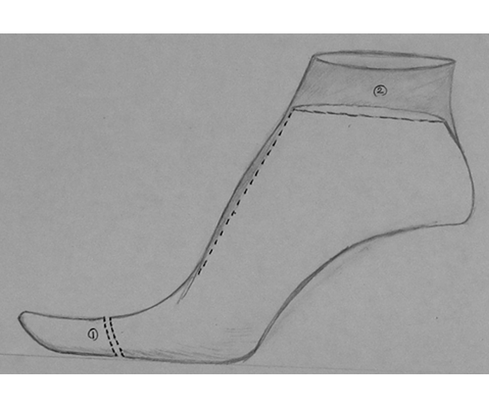
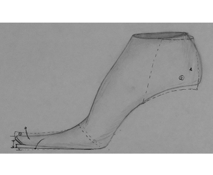
 Figure 10.9a(i) widening or tightening the toe part; modification on instep and waist (iii) modification of the back curve (4) modification of the shank profile, which is a part of the last bottom profile
 -
 Figure 10.9b(i) shortening or elongation of front part (ii) transforming between shoe and boot lasts
 -
 Figure 10.9c(i) Changing the toe spring (ii) changing the heel height
 -
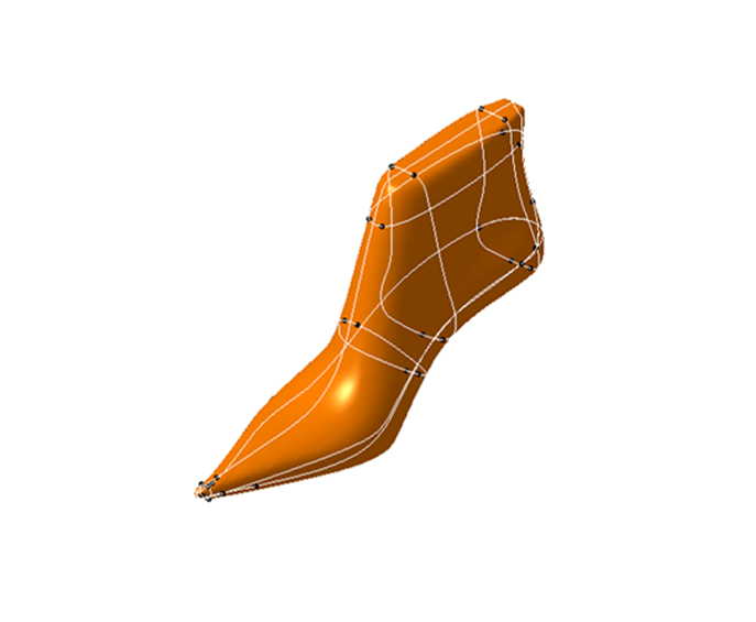
 Figure 10.10Shoe last model interpolating some skeleton curves
 -
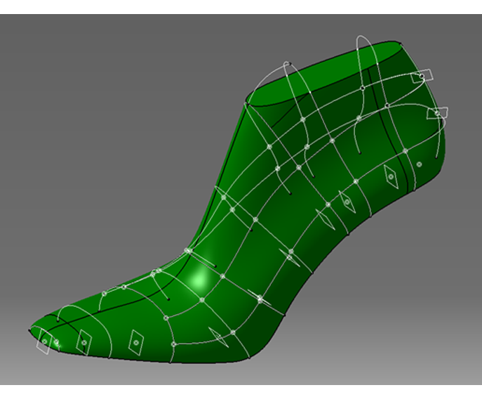
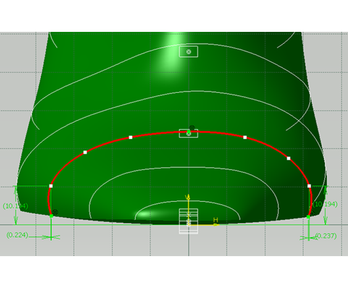
 Figure 10.11Modifications on interpolating section curves can be made by moving curve points (shown as white squares in the figure).
 -
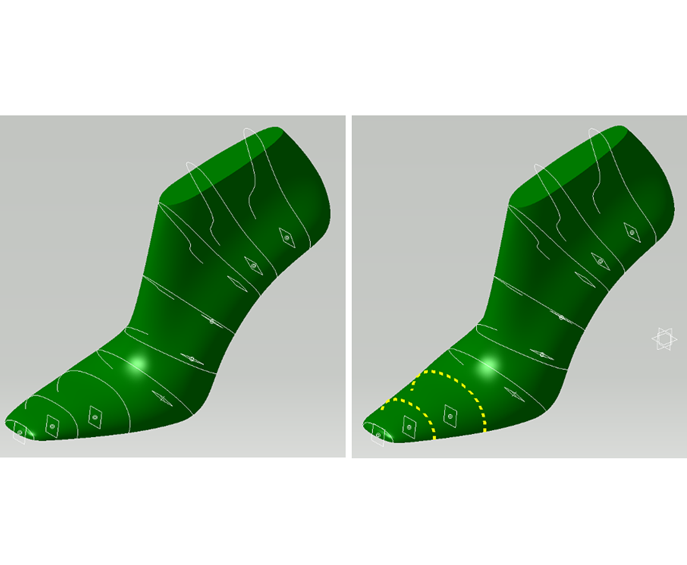
 Figure 10.12(a) Shoe last model showing interpolating section curves (b) The two curves shown in dashed line were modified, resulting in a slimmer toe as shown.
 -
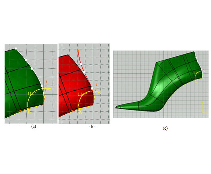
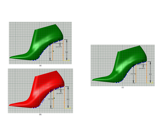
 Figure 10.13(a) The back curve profile of a last (b) Modification of the back curve profile; the shape of the curve, as well as the angle it makes with the last bottom is changed. (c) the modified 3D last model, highlighting the changed back curve
 -
 Figure 10.14(a) The two orange curves indicate interpolating back section curves. (2) The upper back section curve geometry is modified to yield a more square shaped back on the last; here, the modified curve's end points are constrained to stay on the vertical sections curve shown in white, and its mid-point is constrained to pass through the back curve. Continuity constraints on the interpolating surface are guarantee the smoothness of the last surface.
 -
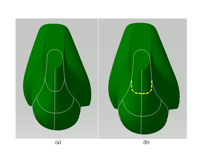
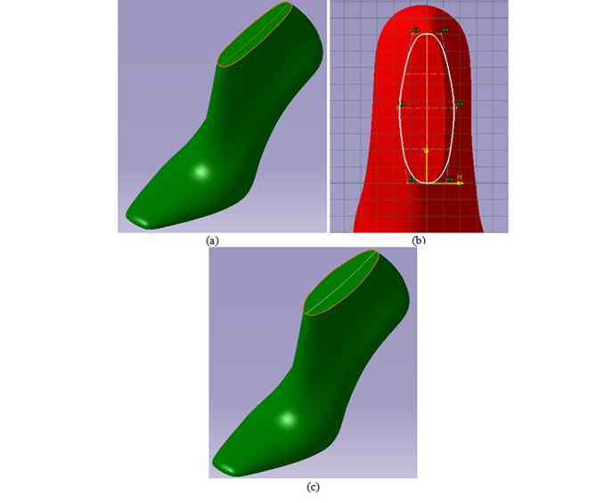
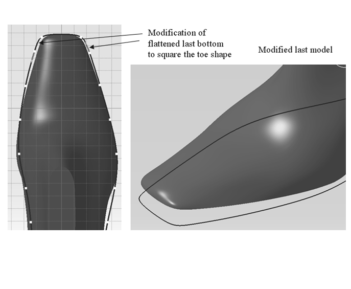
 Figure 10.15(a) Last with top surface profile highlighted (b) Shape modification of the top profile (c) Resulting model of the last
 -
 Figure 10.16(a) Model of a last with the last bottom profile curve highlighted (b) Modification of the last bottom profile curve, and (c) the modified last shape
 -
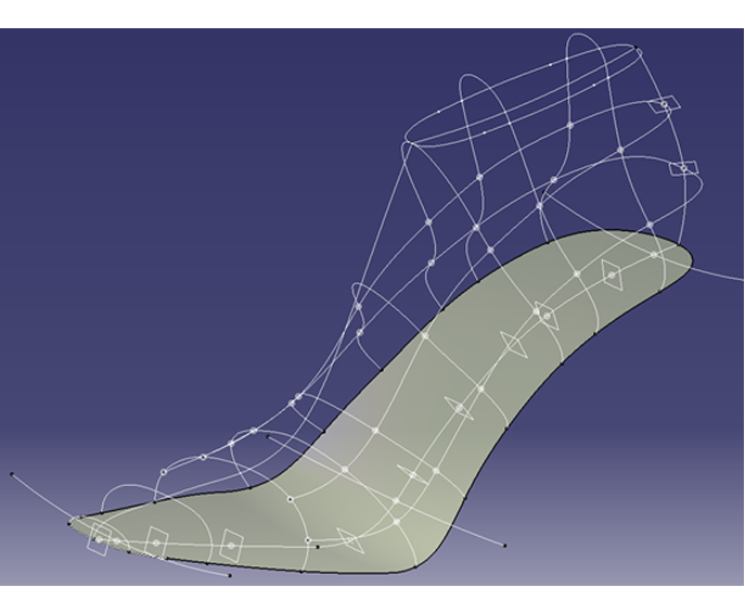
 Figure 10.17One way to construct a CAD model for a shoe last. The algebraic surfaces are constructed by skinning a set of skeleton curves that are held by one or more spine curves. The last bottom profile, the bottom section curves, and the last section curves have spatial relationships; the dots in the figure indicate coincidence of intersecting curves, and surfaces are constrained to pass through the curves. The surfaces patches making up the last body (respectively, last top, and last bottom) have G1 continuity along their shared boundaries.
 -
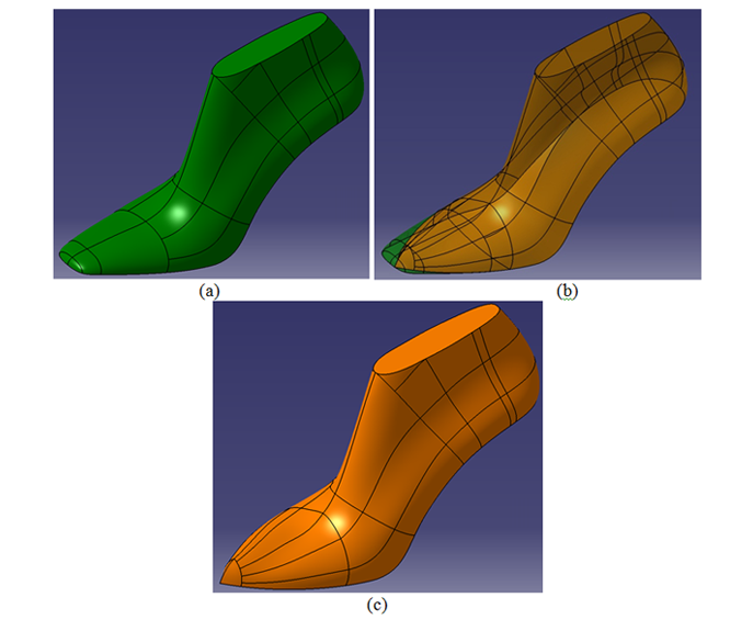
 Figure 10.18(a) A shoe last (b) The toe of a different last is merged smoothly onto the back part of the last in (a), and (c) The new last, which retains the back part of the original merged with the toe shape of the second one
 -
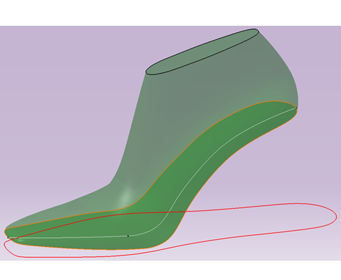
 Figure 10.19A last model showing the last bottom surface, the last bottom featherline (in orange), the last bottom centerline and the surface development of the last bottom onto the bottom plane (in red).
 -
 Figure 10.20Modification of developed profile of the last bottom. Mapping this modification back to modify the last model requires complex computations, possibly involving solving on an optimization problem.
 -
 Figure 10.21(a) A shoe last showing the clear edge of the last except in the smoother inner arch region (b) The last center plane
 -
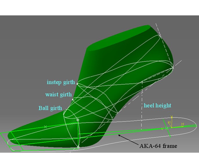
 Figure 10.22US last measurements illustration
 -
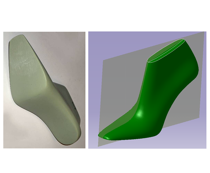
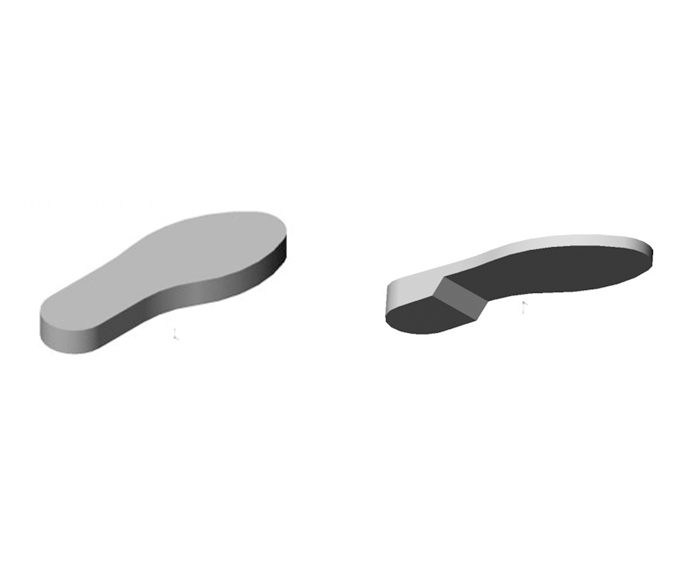
 Figure 10.23(a) A shoe last model (b) Surface offset operator on the last bottom surface used to create a 1mm uniform thickness insole.
 -
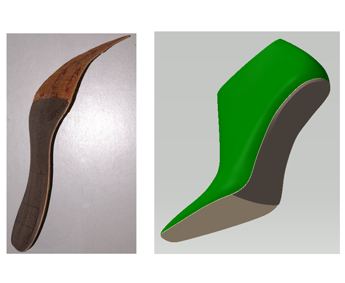
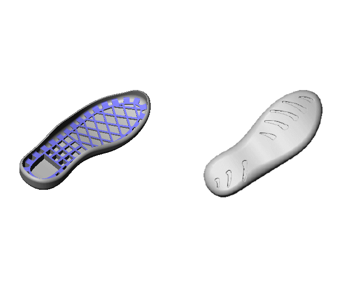
 Figure 10.24(a) Image of a midsole glued to an insole (b) CAD model of a last model along with an insole and a graduated thickness midsole.
 -
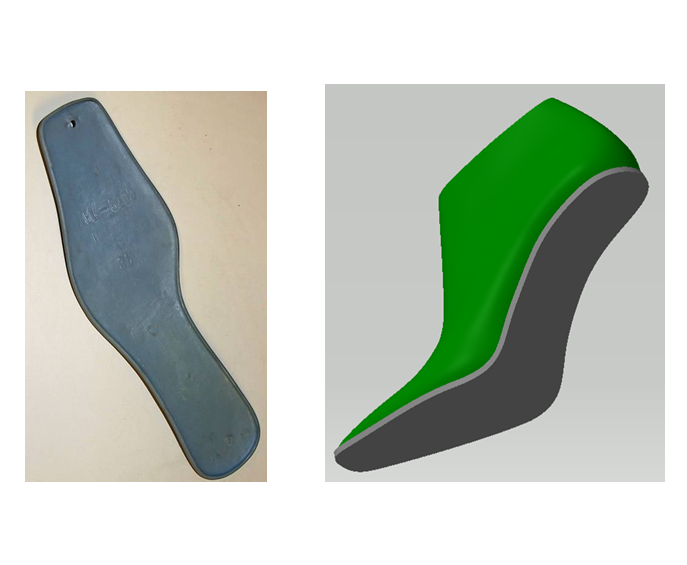
 Figure 10.25(a) Image of simple outsole (b) CAD model showing a last and an outsole covering the insole and midsoles.
 -
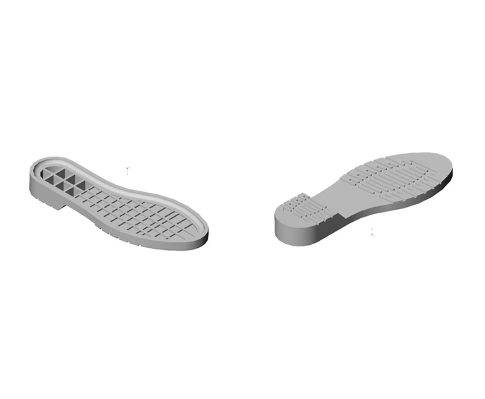
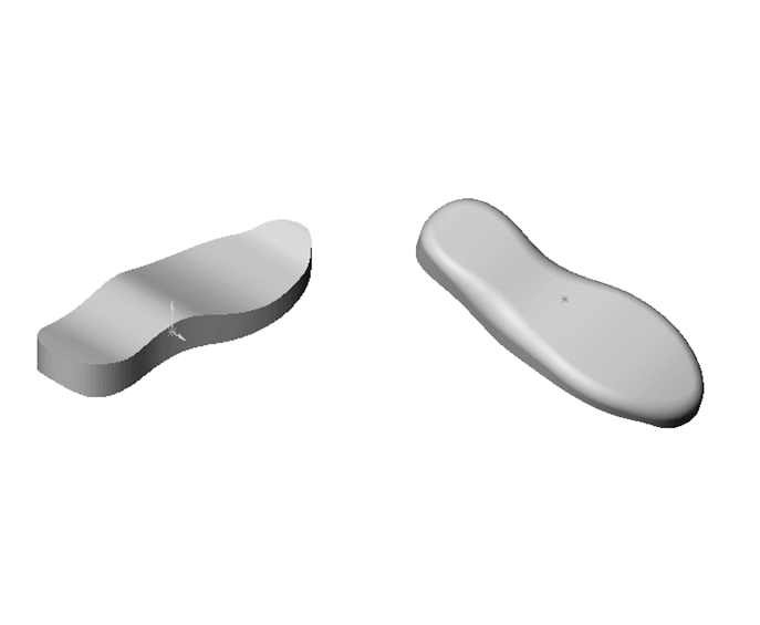
 Figure 10.26Two views of an outsole for a men's dress shoe
 -
 Figure 10.27Initial steps in generation of the CAD model of the outsole
 -
 Figure 10.28Two views of an athletic shoe outsole
 -
 Figure 10.29A variable radius blend operator along the bottom face of the (partially completed) outsole model
 -
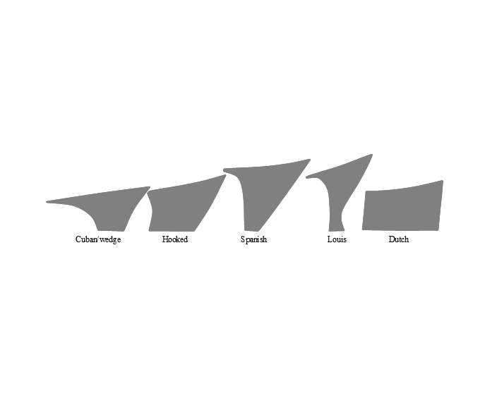
 Figure 10.30Profiles of common women's shoe heel styles (HKPC)
 -
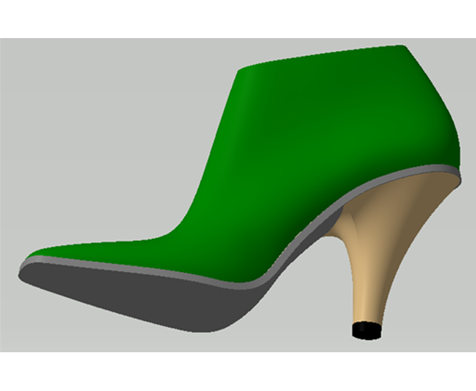
 Figure 10.31A CAD model with a Spanish style heel
 -
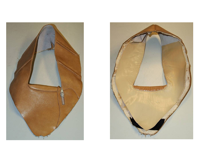
 Figure 10.32Views of outer and inner sides of a stitched shoe upper
 -
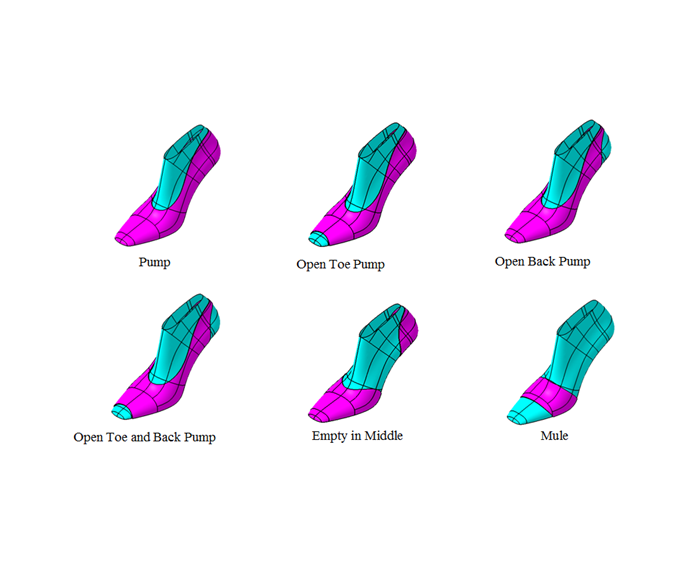
 Figure 10.33Common women's shoe styles
 -
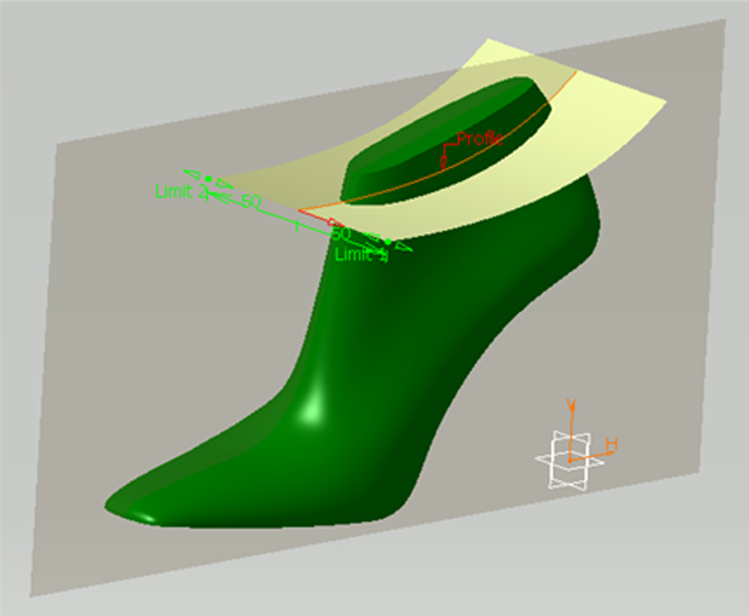
 Figure 10.34Using an extruded surface to generate design curves on the last. The red curve on the last center-plane is extruded to form a surface, which is intersected with the last to yield the required design curve.
 -
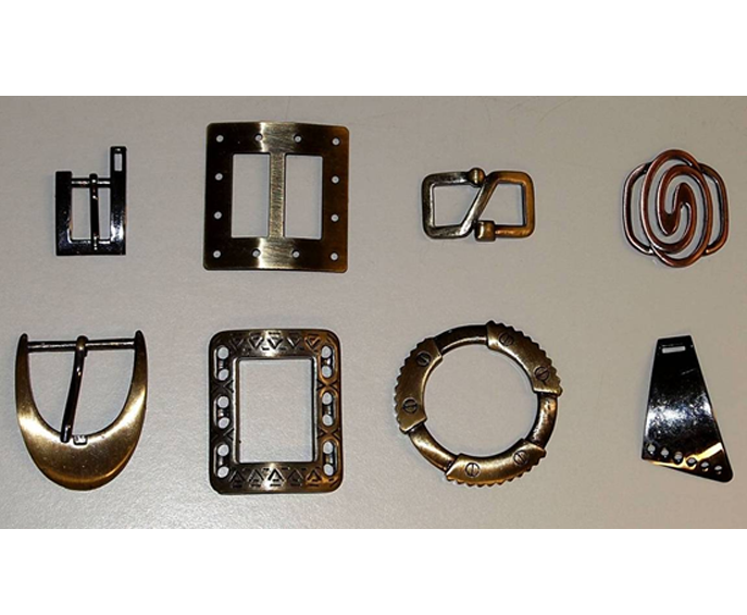
 Figure 10.35Just a few of the countless accessories designed for footwear
 -
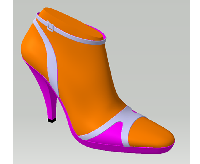
 Figure 10.36A sandal style shoe with a buckle assembled to the ankle strap
 -
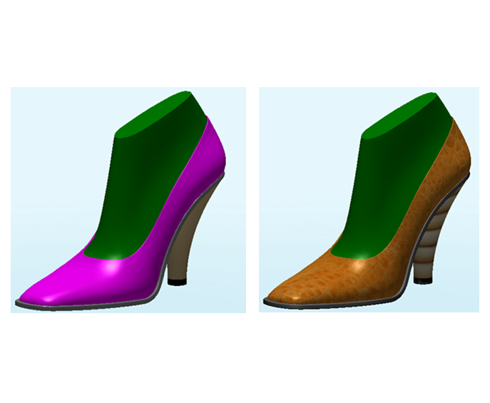
 Figure 10.37(a) CAD model of a shoe (b) The same CAD model rendered with a leather material applied to create a different texture for realistic rendering